
Ladder Diagram For Star Delta Starter
see the delta plc programming full lecture seriespractical programming of delta plchttps://www.youtube.com/playlist?list=PLPtob0wlAlH7oB-uQKo3toTgcl-knwE-UD.

Star Delta Wiring Diagram Explained
During the starting period of star delta starting, an induction motor is coupled to a star connection. The motor is then hooked in through a delta connection once it has reached the required speed.. Off Delay Timer in Ladder Diagram 11m 10s; Retentive Timer in Ladder Diagram 12m 7s; Star to Delta Motor Starter in Ladder Logic 27m 56s.
Control Circuit Operation of Automatic StarDelta Starter of Induction
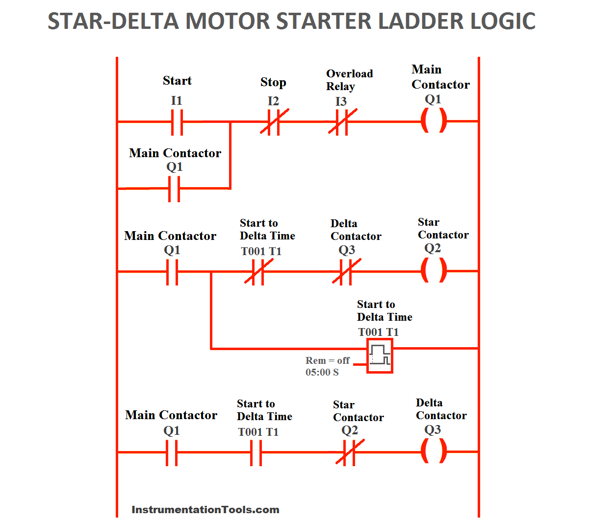
The following section of PLC tutorial will explain the ladder programming for star delta motor starter. PLC program for star delta motor starter : PLC Ladder Logic Rung 1 Main contactor : The main contactor depends upon the normally open input start push button (I1), normally closed stop button (I2) and normally closed overload relay.
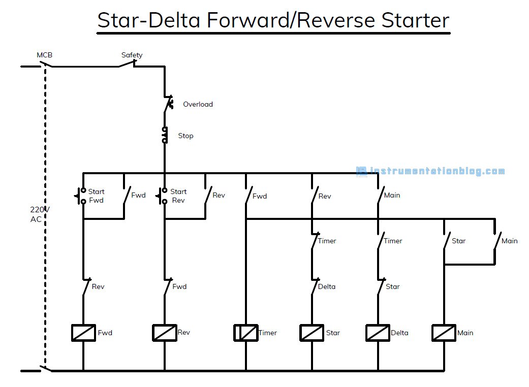
Star Delta Forward Reverse Starter with PLC Ladder Logic Conversion
Two windows will appear on the screen, namely Instruction list mode and Ladder diagram mode. Choose the Ladder diagram mode and maximize the window. Write the Relay Ladder Logic program for Star-Delta starter as shown in power and control diagrams. Compile the program using Ctrl + F7. If there are any errors, correct the program.

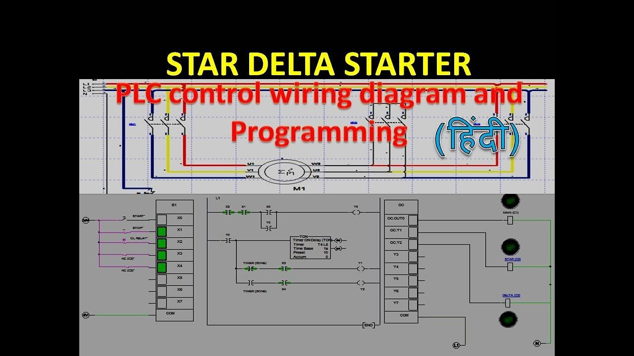
PLC Programming of Star Delta Starter using Selec PLC II Star Delta
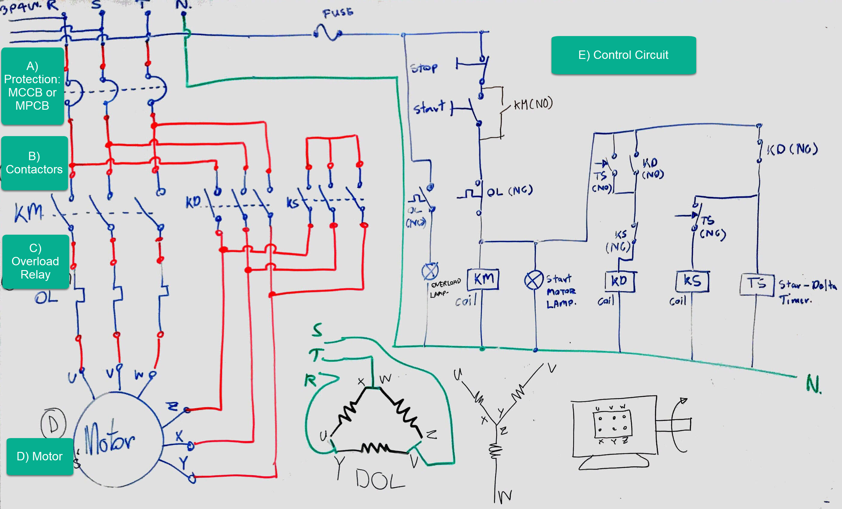
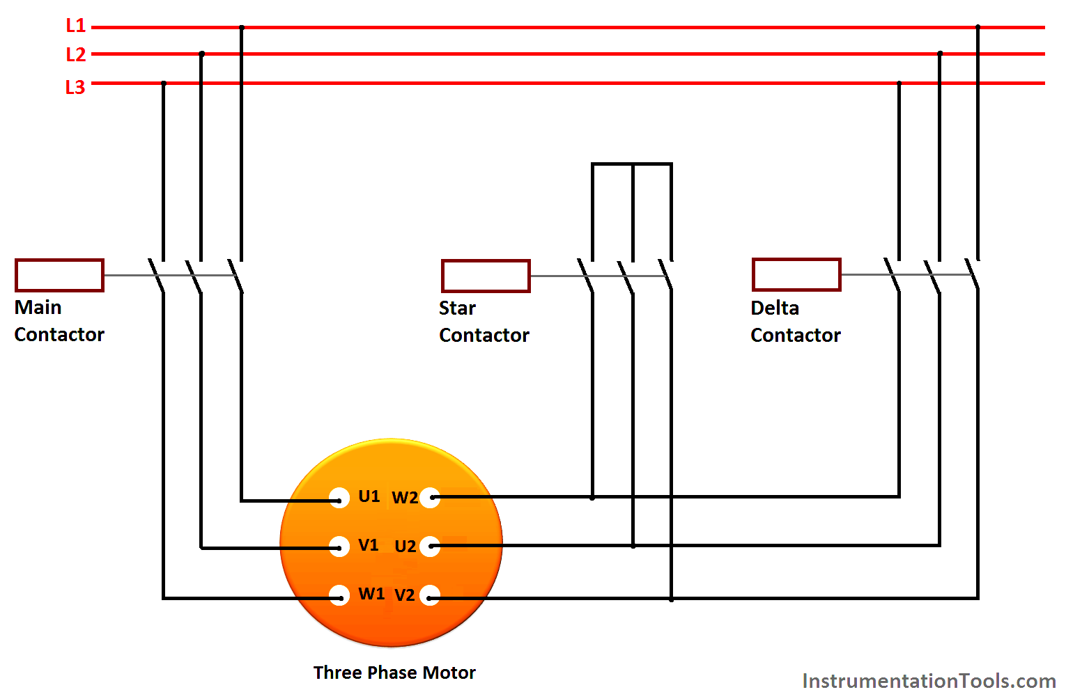
Star-delta motor control power circuit. CAD drawing by ianjonas. Illustrated on the star-delta circuit diagram above, the three-phase line voltage L1, L2, L3 is supplied from the main circuit breaker down to the main magnetic contactor and finally to the three primary terminals of the motor coils U1, V1, W1. Meanwhile, the closing of the star.

Using StarDelta Motor Control (With Circuit Diagrams)
Programming & Ladder Diagram. To implement the star-delta starter motor control circuit using the S7-1200 PLC, we will need to follow the following steps: Connect the power supply to the PLC and configure the necessary input and output modules. Connect the contactors to the output modules of the PLC. The contactors should be connected such that.
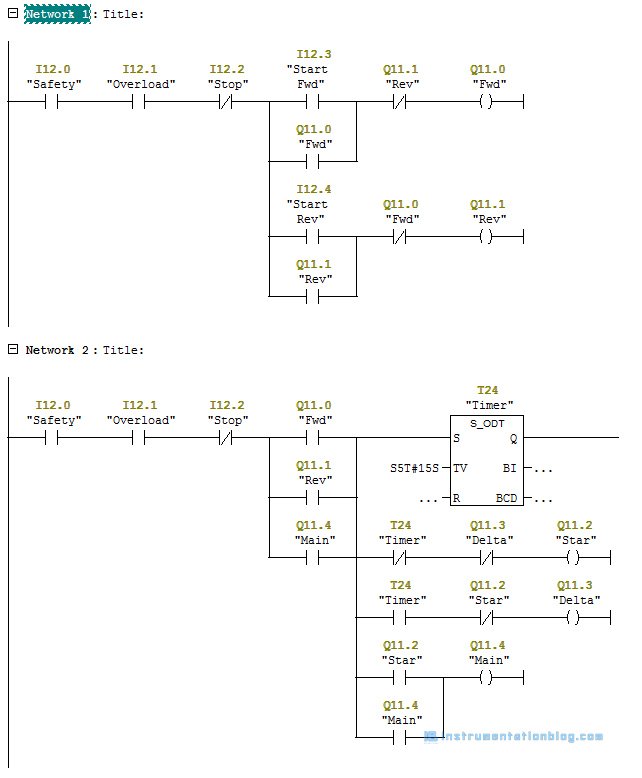
Star Delta Forward Reverse Starter with PLC Ladder Logic Conversion
Star Delta Programming using TIA Portal || S7-1200 PLC

Electrical Wiring Diagram Star Delta Control and Power Circuit Using
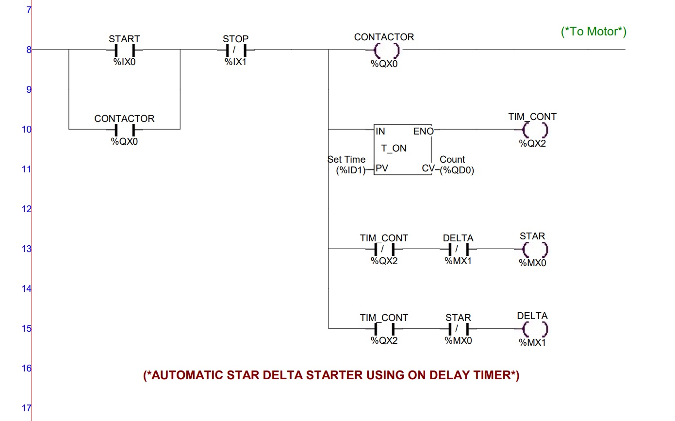
Ladder Diagram: Making the Ladder Diagram: In the there are only two inputs, i.e. START and STOP and four outpur coils, CONTACTOR, TIM_CONT, STAR and DELTA. From ladder line 8, a rung is connected with input NO contact, START push button switch (address %IX0), NC contact, STOP push button switch (address %IX1) and a output coil CONTACTOR.

Diagram Ladder Star Delta boat wiring
Star delta starter is the popular method to start a large induction motor at a reduced voltage. Star delta starter means two separate stat of starting. First, the motor starts with a star connection and when it reaches up to 75% to 85% of its full load speed, the motor runs in delta connection. When the motor starts without a Star-Delta starter
The Beginner's Guide to Wiring a StarDelta Circuit Factomart Singapore
A star delta starter is the most commonly used method for the starting of a 3 phase induction motor .in stat delta starting. The switching operation is obtained by controlling the contactor through ladder diagram. The on/off operation should be automatic and its requirement Is seen in the controlling of machines involved with moldings.
PLC Program for Star Delta Motor Starter PLC Motor Ladder Logics
This will include providing a schematic, power and control, PLC ladder, and wiring diagrams. We will also explain how the star-delta starter works and discuss its applications, as well as its advantages and disadvantages. Table of Contents Working of the Automatic Star / Delta Starter using Timer Operation & Working of Automatic Y-Δ Starter
Star Delta Starter Plc Ladder Diagram Control Circuit Plc Program Plc
At its most basic, the Star Delta Motor Starter Ladder Logic Diagram is made up of three lines representing three different phases of power - start, run, and stop. Each line represents a different sequence of events, and each line can have additional logic elements to represent additional conditions.

Simulasi ladder diagram StarDelta YouTube
Wiring Diagrams Power Diagram Control Diagram Ladder Diagram Programing the Star Delta Starter Using PLC Working of the PLC Program for Y - Δ Motor Starter using Timer Firstly, the PLC reads the status of two buttons - ON and OFF. Once the ON button is pressed, the timer Starts counting time.

Diagram Ladder StarDelta ( CXProgrammer ) YouTube
In the diagram of Power Circuit of Star Delta Starter, U2 and V2 of 3 phase motor should be connect to 4 and 6 respectively instead of U2 and V2 are connected to 6 and 4 of Delta Contector KM2. There is minor correction is require to change (printed in boxes) sequence of 3 phase wires from W2 V2 U2 to W2 U2 V2 to get Delta connection properly..
PLC Program for Star Delta Motor Starter Instrumentation Tools
VIDEO HIGHLIGHTS:How does a star delta starter work?What is star delta Connection in PLC?What is PLC ladder diagram?What is ladder logic with example?For mor.

Star Delta Forward Reverse Starter with PLC Ladder Logic Conversion
The ladder logic for a star/delta motor control is quite simple, and that is one of the advantages of using a PLC for motor control. Ladder diagram of star/delta starter with a Mitsubishi PLC. Another great example of how to use a PLC for star/delta start of an AC motor is example #5 in the PDF file below.
